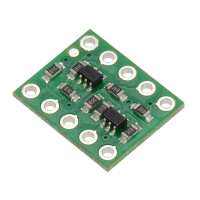
“I needed a way to be able to read a PWM signal from a 12v circuit using a GPIO on a Pico. So that's a 12v to 3.3v logic shift. Just received this board in the post, it's the size of a 10pin chip, Wired up the LV side, to the 3.3V pin on the PIco, and the GPIO pin directly to LV1. Then applied a 12v power to HV and the pwm signal to H1. Connected the grounds of the pico and the 12v circuit together, and hey presto was able to read the PWM circuit without any problems. (My PWM signal is at 50Hz) This little board has just saved me a huge headache trying to figure out how to read this signal without frying my Pico in the process.”